
Troubleshooting or testing mobo for error to see if it works can be carried out at home easily using a simple multimeter to test a variety of circuits and diagnose common electronic problems. All you need to do is learn how to test your motherboard with a multimeter, as it’s the easiest way to find out what’s wrong with your motherboard. The below article provides you with a step-by-step guide on how to test a motherboard with a multimeter.

Looking for a quick answer? You can easily use a multimeter to test your PC motherboard for both short circuits and DC voltage at home.
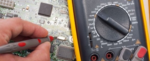
How To Test A Motherboard With A Multimeter
For Short Circuits
Drain Power From The Computer
Unplug your computer and wait a few minutes so that any extra charge can drain. You can also try to press the power On button to quicken the draining of power. Typically, when you press the power On button, the computer drains power from the capacitors as it tries to start.
However, this might not be effective if the problem is with the power button. Place the multimeter to the lowest ohm configuration (about 200) and together touch the leads of the probe to read zero on the meter.
To the uninsulated metal of the computer, the chassis touches the two leads. Typically, the Zero reading should be similar.
Test The PSU Ground Pin
Disconnect the ATX connector from the computer motherboard carefully. Keeping the black probe on the chassis of the metal, look at the PSUs A/C ground pin using the red lead and the pins of the black wire to the D/C connector, which all should read zero.
Check The Colored Wires Reading
Put the black lead in the box and look at the colored wire pins values from the Direct Current connector using the red probe. All colored cables must read 50 or more.
Test The GND Pins
Disconnect the CPU from the socket of the motherboard. When referring to the pin numbers on the board connector, you should use an ATX 20-pin chart.
Put the black lead in the chassis, and using the red lead, carry out a test on the GND pins on the connector of the motherboard – odd number pins from 3-15, and then 16 and 17 must go back to a zero reading. Any other readings show a possibly defective connector.
For DC Voltage
Connect The Computer To Power Supply
The first step is to ensure the 20-pin ATX connector is connected if you had disconnected it. Then, hook up the computer to an AC power outlet. The multimeter should be set to 20V DC before starting to test. Use the black multimeter to probe the connector’s backside, and the black probe must be in contact with GND pins (15, 16, 17).
Test The PS On Values
Using the red probe, proceed and probe these pins (look for readings shown in parentheses): pin 9 (purple, VSB) must be 5V (all the other reading shows an issue with the power supply); and pin 14 (green, PS on) must be 3-5 volts. The PS On value must drop to zero if you press the PC power switch. Other readings show a defective switch.
Test The Power OK Button
Check pin 8 (gray, Power OK) with the red probe, which must be greater than 2.5V; this indicates that the computer can start. When you press the reset button, the Power OK value drops to 0 and then returns up.

How To Test Laptop Motherboard With Multimeter To See If It Works
The main task is a visual inspection of the motherboard. The main cause of motherboard problems or disappointments is a blown or swelling capacitor. Check the top part of each capacitor for swelling or leaks, which indicates a blown capacitor.
Capacitors are mainly the cause of problems with your PC’s motherboard. The hard drive may show signs of malfunctions, such as missing files or blue screens. However, the motherboard unexpectedly stops working.
- Conduct a visual inspection of the CPU, which includes removing the CPU from the PC.
- After removing the CPU, look for bent pins which is an afterthought that embeds the motherboard.
- Track down the bent pins, which likely causes PC and CPU problems. Plugin your computer and turn it on.
- On the screen, look for the BIOS manufacturer’s name, for instance, AMI, Award, or Phoenix.
- If the computer starts, it’s OK.
- The beeps arrangement and the file number that takes place when the PC performs an individual power test is also known as the POST test. The number and beeps grouping that indicates CPU damage depends on the BIOS manufacturer. Therefore, consult the documentation that came with your PC or contact a PC specialist shop to determine if the POST indicates CPU damage.
- Inspect the CPU fan to make sure it is working and replace it if necessary.
Final Thoughts About Testing Motherboard For Errors
You need to be patient and cautious when testing mobo for error to see if it works. Mainly, it’s because it single handedly controls and regulates the CPU functions, and any problem could easily result in a total dysfunction of the computer. Hopefully, the above guide will help you understand how to test a motherboard with a multimeter at home. Remember to follow the manufacturer’s instructional manual when testing.
Table of Contents
Pingback: How To Test A Motherboard Without A CPU (Can You Do It?)